Monday, July 31, 2017

Day 18

Almost forgot tomorrow I can bring a friend. I've contacted a past year intern -- not sure whether he would like to come.

It's Monday today so I felt hard getting up this morning (even forgot to set the alarm). I majorly worked on double lens system today. I did some researches on the double lens system. Basically, I needed to solve equations for each lens separately. I put another convex lens between objective and camera to display the whole object in the small CCD sensor.


Lauren left me two different convex lenses. She said I could pick one and she gave me a hint related to the resolution of the image. So I looked up resolution limitation of the lenses. It looks like according to two equations, the longer the focal length, the smaller the NA,  and higher the resolution. I will ask Lauren whether this is correct tomorrow. Even though I thought I should use the longer focal length one, I still used the small one with lower f, since it was much easier to adjust the height and position. 


Sunday, July 30, 2017

Pump-Probe Imaging Project Outline Draft

Pump-Probe Imaging project Outline     

Yizuo Chen

1. (Title)Pump-Probe imaging for analyzing femtosecond laser-induced structure changes
Two images: surface before hitting by laser; surface after hitting by laser(final state).
2. (Summary)
·         Femtosecond laser has been widely used for optical and photonics fabrication
·         The pump-probe imaging system was constructed to investigate silicon ablation process.
·         (*)The images of surface structures at different delay times were collected and analyzed.
·         (*)The patterns of surface structure changes reflected effects of femtosecond laser on the silicon ablation.
3. Femtosecond laser has been used on material removal in various ways.
Several images of femtosecond laser cutting glasses, nanostructure, etc.
Left: Combine the real system and the model image
Right: the model diagram with specific lengths and measurements.
5.  Dynamic change of optic substrates was investigated  by changing the delay time
6.  Zero time delay point: Intensity autocorrelation and Second Harmonic Generation
Show the equal distances of pump beam and probe beam generates SHG
Image: zero-time delay setup diagram
7. The laser intensity was determined through calculations.
Show the calculations of the Gaussian beam energy by using propagation formula and focus equation
8. A real image capture camera was built by using a CCD camera and an objective.
Show the inverse Focus equation used for putting the objective.
Show images of investigating principles of camera imaging.  
Show how to control the time delay line through software, CCD camera, and delay box through Labview or Matlab
Image: connect the delay box and oscilloscope box
Front panel programming to set up the triggering and delay time.
An attempt to send CCD and laser box signals using delay box.
11. CCD camera was connected to a laptop by using Matlab scripts.
Frame rate and exposure time were set and the trigger method was tested. All the images will be sent to a folder and be analyzed automatically.
Image: plotted graph of the pixel sums of testing in a dark room with light.
Image: diagram from Labview.
An attempt to connect all the systems together.
13. (*) The pump-probe images reveal the femtosecond laser material interaction mechanism. Show the sample images captured by CCD camera in different delay time.
14. (*) Comparison algorithm was used to show the periods of the sample surface structure evolution.
Diagrams to show the comparison algorithm
15. (*) Show the patterns found by using the algorithm
Images to show the diagrams or data.
16. Conclusion.
·         Femtosecond laser has been widely used for optical and photonics fabrication
·         The pump-probe imaging system was constructed to investigate silicon ablation process.
·         (*)The images of surface structures at different delay times were collected and analyzed.
·         (*)The patterns of surface structure changes reflected effects of femtosecond laser on the silicon ablation.

17. My Contributions.

                  ·         Controlled Delay line software to find the zero time delay point.
·         Determined the laser intensity by writing Matlab Code for pump beam spreading and focusing.
·         Wrote CCD camera routine in Matlab to set CCD camera’s triggering and to save all the images to a computer automatically.
·      Worked on Delay Box Front Panel Programming and Tested it with an oscilloscope box to generate time delay between signals.
·         Worked on camera imaging principles in order to develop CCD camera to a real camera.
·         Wrote Probe beam propagation code in Matlab to calculate the change of probe beam’s spot size as well as the position of the objective
·         Worked on constructing the system on Labview; (stopped by the lack of visual acquisition software).
     
*: not sure whether can be done on time


Saturday, July 29, 2017

Day 17

It was a surprise it was Joe's son who held camera yesterday during the interview!

After calculating the spot size during the beam propagation, I found the spot size in the sample would be around 9mm, which was much larger than the aperture of the objective. The position of the objective was on the way before the beam even reached the sample.  If my calculations were correct, we might have to change the beam expanding process to decrease the original radius of the laser beam.

We found the exposure time was actually 2 ^ n sec (n is the scale on Matlab); thus we can just set a relatively long exposure time and capture the laser beam in a very dark room. So we can see the final integrated light on camera.

Next week I will work on decreasing the spot size and testing more on the exposure time.

Thursday, July 27, 2017

Day 16

Today we were supposed only work in the afternoon and have a field trip to Mees Observatory at night. However, my mom sent me here early so I was able to look at Dr. Qiao's comments on my outline. I also started putting my presentation slides together. After I drew all the paths and put names of optic instruments on a photo, I realized the objective was not in the photo --. I also asked Lauren some math notations on a textbook so I was able to understand the formulas better.

We continued working on building the camera again. After attempting trying different light intensities as well as different filters, I used my phone as the object and it worked pretty well. By the way, when we were testing our camera, we were being interviewed. I have no idea what I talked about; I just know I was so nervous when I was facing two enormous cameras.

I felt so happy that the camera actually worked.

A picture captured by the camera:


Wednesday, July 26, 2017

Half Way!

We are half way done with our internship!

This morning Lauren gave Henry and me a really intriguing challenge: to make a real camera by using CCD. CCD camera is only able to gather the intensity of the light, functioning similarly to a sensor in the real image capturing camera. The whole morning we were basically trying to figure out how the objective worked and camera imaging worked. After that, I used Focus Equation again and used inverse propagation formula to predict the position of the CCD. Later Lauren told me that what she wanted me to do was actually to make the camera work for natural light first. So classic "1 / d0 + 1 / di = 1 / f " equation appeared again and Henry and I started solving system equations. I was solving it manually which made things way more complicated comparing to what Henry did by solving in Matlab.

Finally, we actually tested our calculations by constructing a small experiment. We changed the distance between light source and a convex lens, and compared the result with the answers we got by using calculations. We found that short distances worked pretty well, but long distances didn't. We would continue working on it tomorrow.

Some images were taken during the experiment (with Henry):


Tuesday, July 25, 2017

Day 14

This morning I was working on the outline. Since I haven't got any results yet, I majorly wrote about what I had done so far in my outline. When I was writing the outline I realized I still didn't quite understand Second Harmonic Generation (SHG). For example, I was not sure why the frequency doubled after the light beam goes through the nonlinear crystal. So I was reading an optic textbook about the SHG. I saw frequency in polarization density doubled but still didn't know how polarization connected to the laser beam. Maybe I will ask Lauren about this tomorrow.

I was also learning some basic Differential Equations. Some values looked so familiar to me since they were very similar to the characteristic roots of recursive sequences. Maybe they are the same in some aspect... I'll learn more about this tomorrow.

Day 13

Labview still didn't work without a proper visual acquisition software, so I was testing the CCD camera using Matlab. Before I started, I set camera's exposure time and frame rate. The Matlab codes I wrote were able to make CCD camera capture 200 pictures and save them in a certain folder and analyze these pictures automatically.

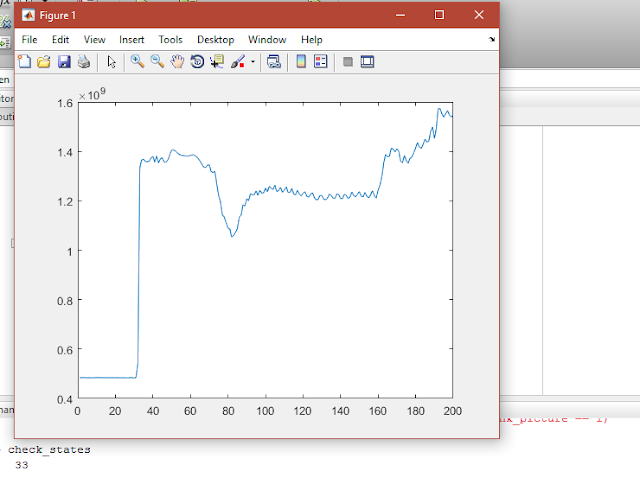
I made a dark room and asked Henry to turn on the light after I started camera capturing the pictures. The sums of all the pixel values in each picture were printed into a .txt file. Obviously, the brighter the room is, the larger the sum will be. we could tell when the light was turned on after plotting all the sums on a graph.


Friday, July 21, 2017

Day 12


It's pretty coincidental that Joe introduced us Labview software this morning and I worked on my project using Labview all day. Labview reminded me of a virtual network builder I used before. Both can be used to construct a system by moving operation boxes and connecting wires between the boxes. Lauren was looking for the connectors, so Zhila and I were learning the Labview. 

We found a tutorial online and we learned the software very fast. Then I was connecting the CCD by connecting the boxes on the diagram. The installation of the drivers and add-ons cost a lot of time. In the end of the day, we were able to grab the pictures, but we still need to work on the picture display next week. 


Thursday, July 20, 2017

Day 11

Today I was working on testing the delay box, and I was using an oscilloscope box to test. I read the delay box manual again and Lauren taught me how to use the oscilloscope box. It was a very heavy project and I tested different cases over and over again. Even though on the manual it says the voltage could range from -36V to 36V, the maximum voltage I got was only 4V. The delay box has four output types and I tested each type. Finally, I figured out how to change the delay time as well as how to make series of triggers. But I didn't know a better way start and stop the pulse besides turn on and turn off the whole delay box. I felt happy that I learned how to use these two important instruments.


Wednesday, July 19, 2017

Day 10

Today I spent most time writing code. The first time I connected the CCD camera with my laptop by programming in Matlab. After CCD camera captured images, these images would be automatically saved in a folder. We could turn on the laser beam, and we could start the CCD camera now. However, a very tough problem came to us: How to make CCD camera capture the image at the exact time when a single laser pulse reached CCD camera's surface? It would be easy to solve if we could just turn on CCD first and take pictures all the time until capture the single laser pulse, but the frequency of our CCD camera is too low. So we need to come up a way to emit the laser pulse and turn on the image at almost the same time.

We gradually realized we had to solve this question by using computer and machines. We could not use our hands to click two "start" buttons (one for laser box, one for CCD camera) at the same time since the time for probe beam to travel through its distance is about 1e(-8) s -- much shorter than human's reaction rate. Lauren gave me four possible solutions and I needed to decide which one would work the best. Since the laser's software does not allow us to set up the time to start, we decided not using that software. After discussing with Lauren and Zhila over and over again, we finally narrowed the four choices down to two: either connect both CCD and the laser box with a delay box then connect delay box with a computer, or connect CCD with a computer and connect the laser box with a delay box separately. After that, I was reading the manual of the delay box.


Tuesday, July 18, 2017

Day 9

This morning Lauren gave Henry and me a lecture on Gaussian beam propagation. I realized that the laser beams spread all the time when they go through space. Then Lauren told Zhila and me what to do next on the pump-probe project. We could not place the CCD camera on and collect data now for two reasons: first, we didn't know what intensity we needed to use for this experiment in order to ablate the Silicon surface; secondly, we could not gather image manually. Since laser pulse travels very fast and frequency of CCD camera is relatively low, we would not be able to know when to take pictures after a laser pulse was emitted. 

Then we came up with solutions for each of the problem. We had known the minimum fluence we needed to ablate the silicon surface. In order to get the minimum energy, we only needed to know the spot size on the sample. Zhila and I measured the total length of the pump beam, then we used Gaussian beam's propagation formula and focusing equation to solve the spot size. Finally, we found the theoretically correct answer. 

The rest of the afternoon, I was playing around with a CCD camera. Tomorrow, I will work more on writing Matlab code to connect the CCD camera with computer. 

Monday, July 17, 2017

Day 8

This morning Joe asked Gerry and me to introduce our projects. I basically talked about the things I wrote in my abstract and I messed up a little on what I wanted to say.

Today I worked on the abstract, since Lauren sent me some more suggestions this morning. I found it was so hard to use the relevant words on my paper without repeat the same words. I received a powerpoint from Dr. Han during the weekend, so I was able to match the diagrams with the real settings first time. I didn't meet with Lauren all the day because I visited Visual Perception group lots of times today and worked with Gerry and Dr. Pelz on algorithm updating. Pretty sure I will stay in lab tomorrow since I'll continue working on setting up CCD camera.


Sunday, July 16, 2017

Abstract Draft

       
Abstract Draft

      Femtosecond laser has been widely used for optical and photonics fabrication due to its extremely short pulse duration and high intensity. Ultrafast pump-probe imaging is used to visualize the dynamic phase changes of optical substrates (silicon, silicon carbide, glass, etc.) by splitting the femtosecond laser beams into pump beams and probe beams. Pump beam (high energy) ablates the sample to remove the materials by direct vaporization. Probe beam (low energy) reflects from the sample surface to a CCD camera to give an image of the surface structure after a delay time. After calibrating the zero time delay point, different surface structures will be observed and gathered by changing the time delay line. Laser-induced structural changes in optical substrates will then be dynamically imaged and characterized by analyzing the surface structure.

Day 7

I had a presentation with Henry and Cayla this morning. We could not find an empty conference room around the building, so we used a room in graduate student office instead. I didn't prepare for it, so I just talked about what I learned this first week and how my project looked like. Maybe I should make some powerpoints next time. Anyway, I think it was a very good preparation for my final presentation.

Since I didn't have serious tasks to do, I visited visual perception group to see what they were doing now. While personally I'm very interested in computer programming, I went there also to learn how to detect and analyze the images which I might need to use on the images gathered by CCD. My brother sent me an OpenCV tutorial; Then I was reading the OpenCV tutorial. I realized the images could actually be split into tons of pixels and then analyze each pixel by comparing it with the pixels around it. 

It was a surprise that Lauren came back, and she gave some suggestions on my abstract draft. Lauren also told me that the laser could not directly go through CCD, which might destroy the CCD camera. I read a sample paper written by Lauren which was a good sample for writing an abstract explicitly.

I hope that next week I can learn how to put the CCD camera and how to collect the images, after which I'll see the real changes of the surface structures. 

Thursday, July 13, 2017

Day 6

Neither Cayla nor John was here today, so Henry and I had to decide what to do ourselves.

I felt very happy that Dr. Qiao sent me a new reference, so I spent time reading it. The paper explained the functions of pump beam and probe beam so I was able to know why we only use CCD to take pictures of probe beams. I was interested in the materials of the sample and I thought this would be a very good topic for future research.

Then Henry and I had a view of Cayla's project; there were so many mirrors and lens on the table. After that, I introduced the project I was working on to Henry.

After lunch, I received an email from Lauren about the abstract. She asked Henry and me to send a draft to our dropbox by the end of today. We felt it was not a problem since we still got four hours to work on it. We walked around the building to collect the outline samples. Finally, we finished it on time.

Today was a very relaxing day without many tasks. Henry and I discussed lots of things, from card game to FFT, and we were able to know more about each other.


Wednesday, July 12, 2017

Day 5

This Morning we watched an introduction video about imaging science in the group meeting. Yesterday we planned that Henry and I would give presentations today, but the group meeting was canceled so I was able to work with Dr. Han this morning.

Yesterday we had found the position of zero time delay line, and today we would continue to the second part of the experiment. So we needed to adjust the set up of the lab a little bit. Yesterday we used BBO to detect the position where probe beam and pump beam intersect, but today we changed the BBO to the real silicon sample, which was washed at least three times by Dr. Han. Then we moved the BBO and the lens of the probe beam to a place where they would neither block the pump beam path nor change the previous path of the probe beam. After adjusting the positions, we could see that the green probe light and red pump light intersects exactly on the sample. Then we used a green light filter which only allowed green light to go through. We had to put a focus lens after the filter since the hole of CCD was very small.

After we were done with the set-up, Dr. Han gave Zhila and me some suggestions on our future work. I also derived the interferometry autocorrelation equation today; I had never thought the proof could be done by using trig operations.

Here's a picture of our new set-up:


Tuesday, July 11, 2017

Day 4


I was reading the "SPIDER" paper this morning, which introduced the application of autocorrelation. I got confused on an equation about the interference of two waves. I searched online and found the concept was related to the "Fourier Transform Spectral Interferometry(FTSI)", which I had never learned before. Then I went to the Optics Textbook and started reading a chapter about wave interference. After that, I realized that I didn't even know the relationship between irradiance and energy. So I began from basic and finally went through the interference of waves from same sources and interference of waves from different sources, which helped to explain the equation in the "SPIDER" paper.


Since Dr. Han today so I spent the majority of the time working with Dr. Han. Dr. Han presented her project to Zhila and me and explained our questions patiently. Then she taught us how to turn on the laser projector, how to set the proper intensity, and how to keep all the things safe. Then we began to adjust the position of the lens as well as the time delay line in order to determine the zero time delay line. Dr. Han measured the distances of Probe beam and pump beam to predict the position of the zero time delay line; Zhila was watching the green lights to see when the middle light appeared; I was operating the motor to adjust the delay line. After limiting the position into a certain range, we had to type single steps manually in order to get a most accurate data. Finally, we found the best zero time delay line at where the light was the brightest. It was a success :)


Here are several photos taken before and during the experiment:


The lab set up:


The moment when we found the middle green light:


Monday, July 10, 2017

Day 3


Monday is always a hard day to get up on time.


This morning Cayla taught Henry and me about the Fourier transform. After that, I finished the two papers Dr. Qiao sent me earlier and understood how to tell the period of solidification a surface through the photos. Then I was thinking instead of analyzing the laser beam, analyzing the solidification of a surface might be a great project. Then suddenly realize this would become a visual perception task if I needed to write code to analyze the change in the photos over time.


After a while, Henry told me that he had learned Fourier Series, and he started sharing the coefficients formulas with me. I felt so interested in the topic, "Can you really write a function by only using 'sin' and 'cos'?" The curiosity drove me to start learning Fourier Series. I was learning by reading an online tutorial written by MIT. The ways to derive the coefficients were so smart. Perhaps I felt it was smart since it made the idea look so simple, comparing to complicated explanations from textbooks.


Since I will work with Zhila on Dr. Han's project, I got some references from Zhila about autocorrelation. I felt that autocorrelation is a process that uses Beamsplitter and BBO to retrieve the Fourier-transform phase for the waves, or simply to make Gaussian look "better". Then I read a reference sent from Dr. Qiao about the SPIDER which was also related to the autocorrelation.


Unfortunately, I left my lunch bag in my mom's car this morning, so I had to walk to the "Global Village" to buy a pizza. It took about 20 minutes to buy the food, and 10 minutes to eat. Hope I'll never forget lunch bag again!


At about 4 pm Henry and I went to watch a conference meeting, where I got confused on the topic for about 45 minutes. I left early at 4:45 since I would have a concert with Brighton Symphony at night.


Tomorrow I will definitely start working with Dr. Han if I can meet her.


Friday, July 7, 2017

Day 2


I couldn't believe I loved my internship so much that I got up on time even though I went to bed at around 3 am this morning. 

I was so surprised that Cayla brought us three textbooks, one of which I read a lot was Introduction to Optics. Cayla was so thoughtful that she gave us a list of chapters related to our projects so we didn't need to look for the useful information ourselves. I read chapter 4, 6, and 26. I'd read a little bit wave function before, but I realized wave functions could be way more complicated than I thought it was. After learning plane wave equation, I tried to derive spherical and cylindrical wave equations by using what I learned in math class, but failed :(

Without knowing how to solve those complex differential equations, I memorized the equations instead. Then I went over the electromagnetic waves, Einstein A and B coefficients, and Boltzmann distribution, etc.

As I planned early early this morning, I started working on the two papers Dr. Qiao sent me after reading the textbooks. These two papers are related to Pump-Probe project, on which I'm gonna work this summer. One paper is concentrated on the morphological effect of femtosecond laser while another paper talks more about the reflection of femtosecond laser. I understood most setups and procedures in the papers, but I still need to spend more time on some physical equations.

After reading the papers, I was able to watch Dr. Han operating on the laser system. It was truly amazing and every instrument looked so professional.

Finally, I was reading the "ProcessNF shot report 40" and "FluenceMap 40" code and considering how to analyze the laser beams. John helped explain me the Gaussian function in such a detailed way that I clearly understood the concept as well as how to use Gaussian functions to model the laser pulses. Really productive day!


First Day

Today was the first day of the internship. I was so excited and got up around 3 hours earlier than usual, even though I was still worrying about getting RIT on time at 8:45. After a brief overview to the internship, we headed up to the "Red Barn", where we had some pretty interesting and educational team building events. Through these team building events, we were able to know each other and learn how to collaborate better as well as how to view the challenges on different perspectives. 

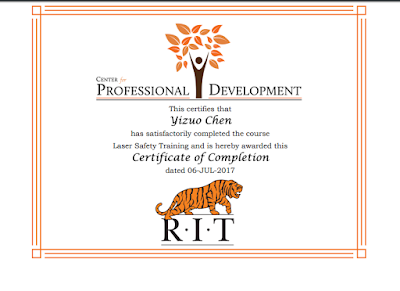
After having a group lunch, Henry and I went to the AOFIM lab, where I believe I'll work for the next six weeks. Henry and I had actually met at the lab group meeting several days ago; we both like programming. After assigning me a computer, my graduate mentor Cayla assigned me a laser lab safety training along with a quiz. The safety training covered some basic knowledge about lasers, such as the types of lasers, the intensity of lasers, and the protections we need to wear. I enjoyed the process because I was learning the basic skills and knowledge necessary for a professional optics worker. As Henry suggested, I should probably paste the certificate here:


After finishing the safety training, I started learning Matlab grammar by reading a tutorial online (a website called "tutorialspoint"). I went over the basic grammars quickly -- from variables to loops, and finally to functions. Anyway, I enjoyed pushing myself to learn a new programming language in a short time period, and here's a fun image from Tutorialpoints:


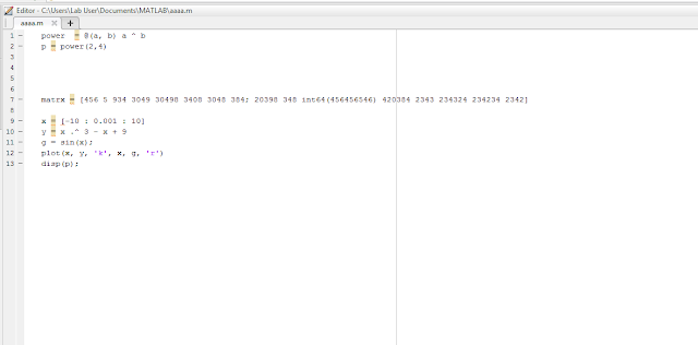
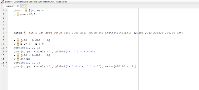
I had heard that Matlab was extremely useful in math calculations and graph drawing, but I've never thought it could be this advanced. I could not imagine how many lines of C++ code were behind every simple Matlab function, and I appreciated the great convenience on graph making and math calculations Matlab brought to us. Here are some screenshots were taken during my learning process:

Plot two functions on one graph:


Subplot two graphs:


find the integral of a function:


Finally, my plan for later today: I will work on the papers Dr. Qiao sent me and read some Matlab functions.